

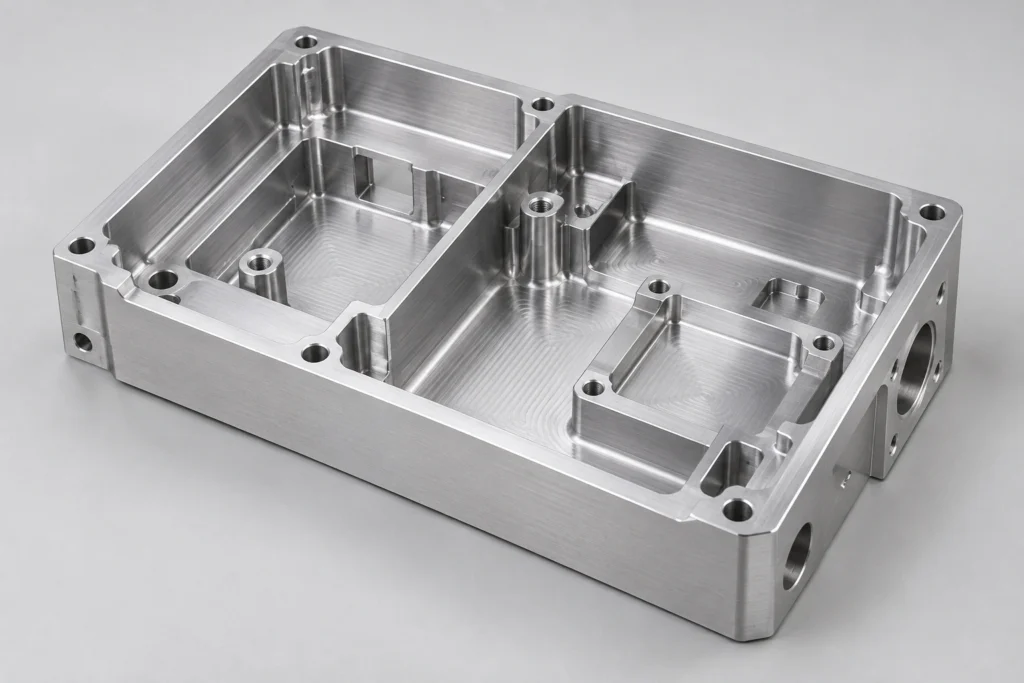
Multi-face geometry
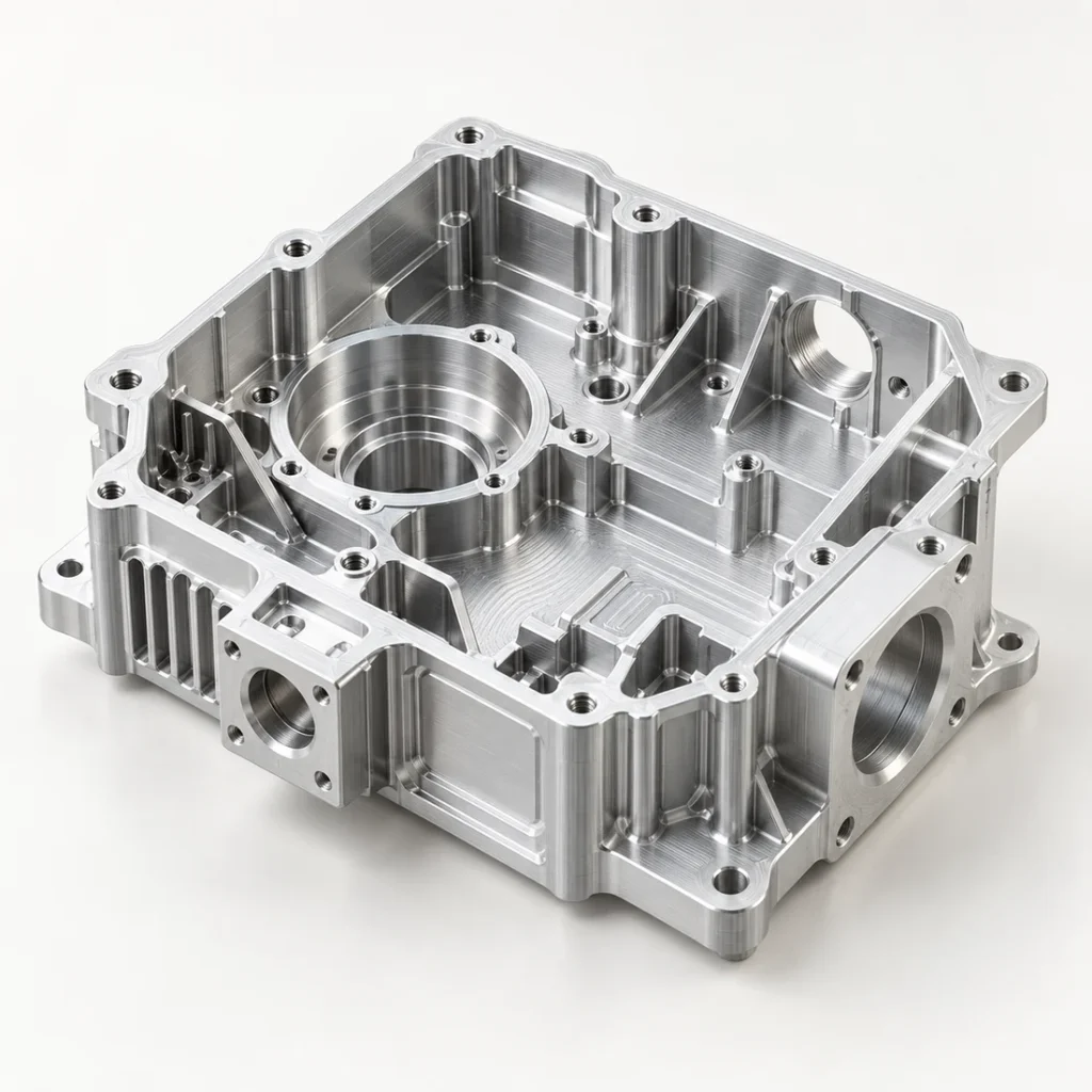
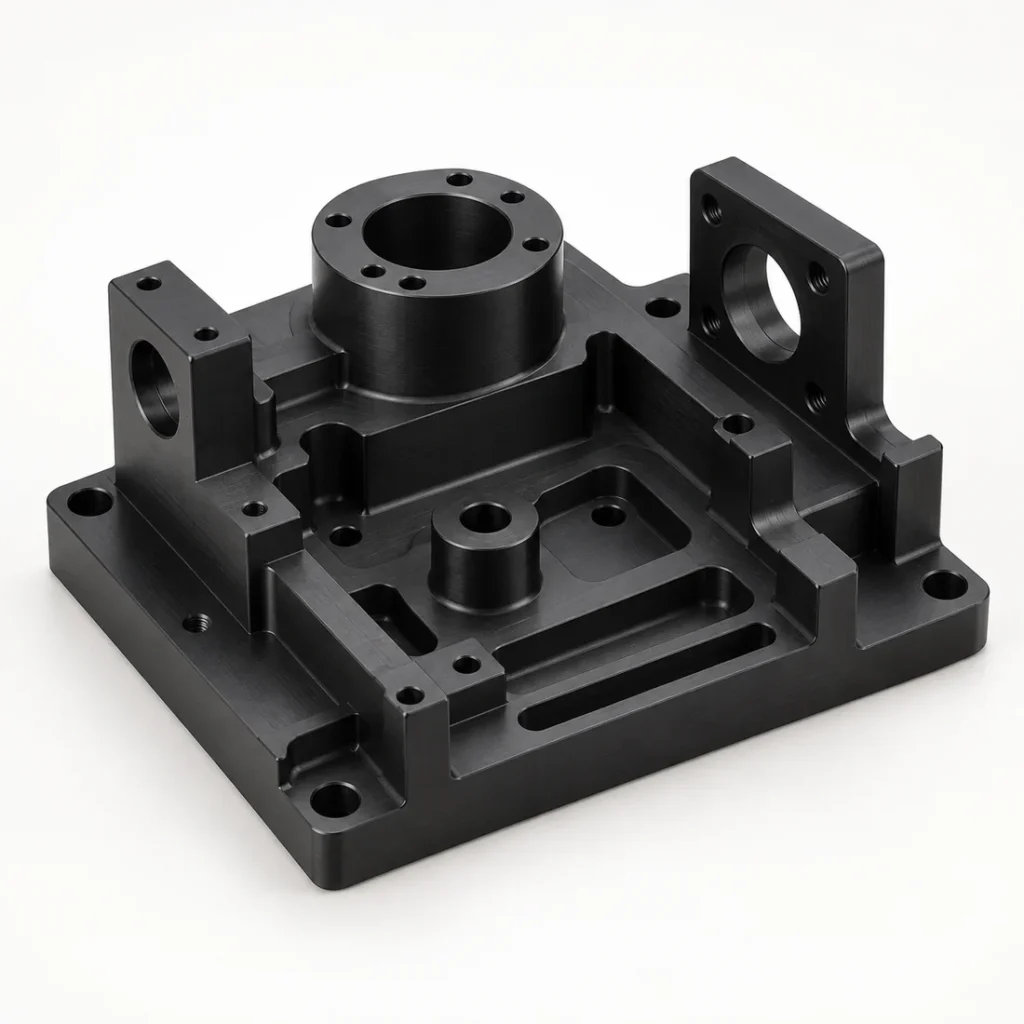
Milling supports pockets, profiles, hole patterns and datum-controlled features across multiple faces.
Precision manufacturing capability
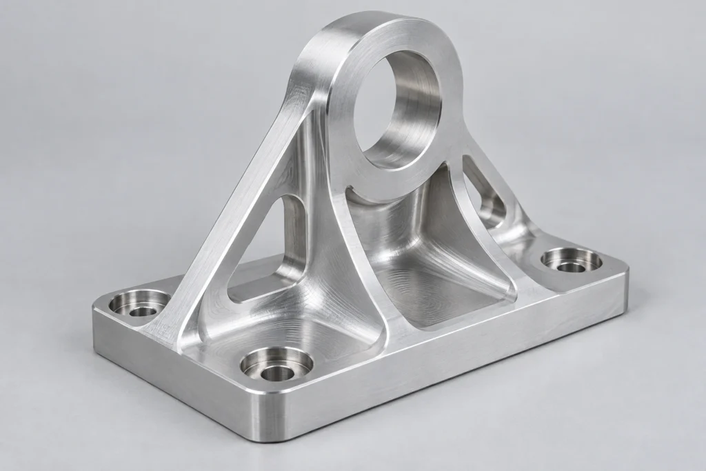
Precision milling for housings, brackets, plates and complex prismatic components.
Request a Quote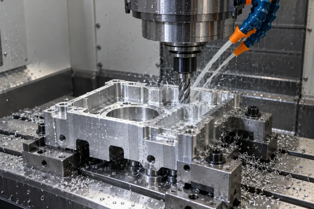
Process overview
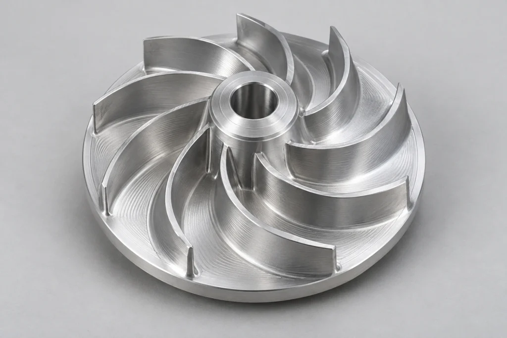
CNC milling removes material with a rotating cutting tool while the workpiece is held in a defined coordinate system. It is well suited to plates, brackets, housings, fixtures, manifolds and other components that combine planar faces, pockets, bores, slots and hole patterns. Three-axis machining handles accessible prismatic features efficiently; indexed or simultaneous multi-axis methods can improve access to angled faces and complex surfaces when the geometry justifies them.
A successful milling plan begins with rigidity. Stock condition, clamping surfaces, tool reach, chip evacuation and the sequence in which material is removed all affect stability. Thin walls may move as internal stress is released; deep pockets can amplify deflection; interrupted cuts can challenge fragile materials. AYBERK reviews these risks against the drawing and expected quantity before confirming a route. Any stated tolerance or capacity is project-specific and belongs in the quotation, not assumed from a general process description.
Key advantages
Milling supports pockets, profiles, hole patterns and datum-controlled features across multiple faces.
Fixture and setup planning are reviewed before production for stable, repeatable access.
Masking and dimensional allowances can be considered before machining begins.
Production methods
Suitable for accessible prismatic features, plates, brackets and straightforward housings.
Used when geometry, access and setup reduction justify a multi-axis approach.
Technical capabilities
Values are published only after AYBERK confirms the applicable process scope. Send your drawing for project-specific review.
Manufacturing workflow
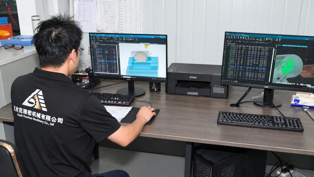
Drawing requirements, critical features and production intent are reviewed before setup.

Machining, in-process checks and documentation follow the agreed project requirements.

Finished parts are checked against the drawing before release and export packing.
Related capability
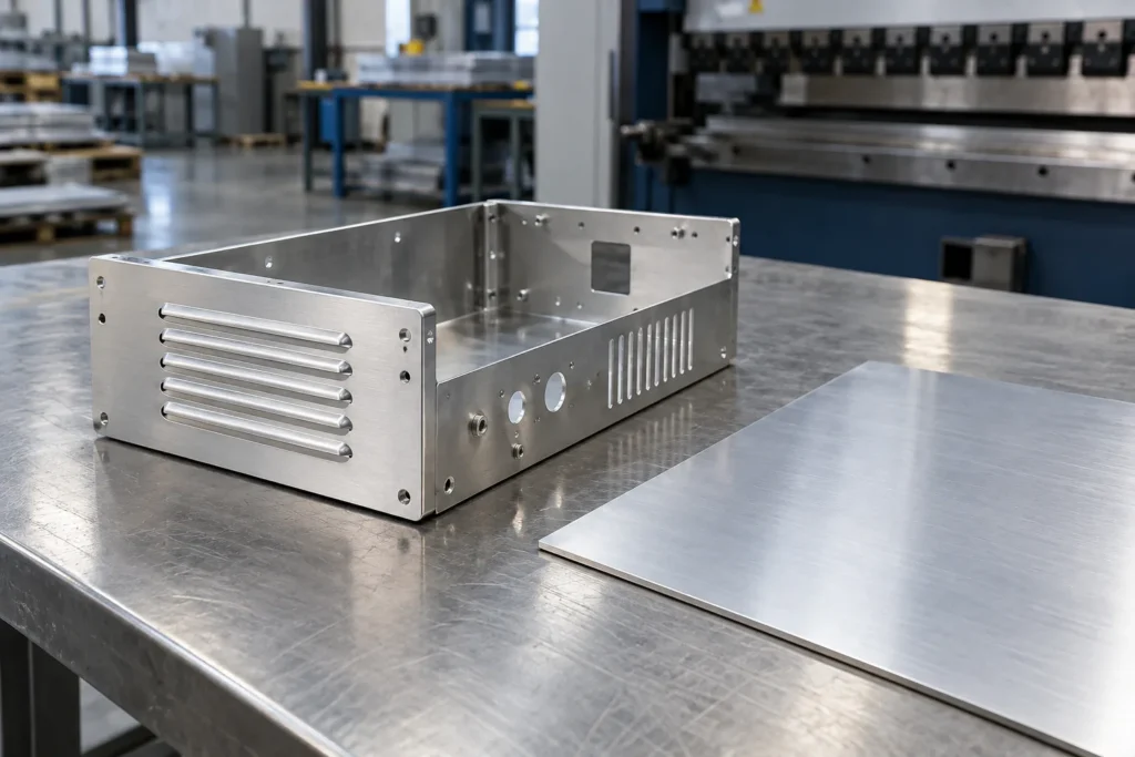
A corrosion-resistant aluminum grade frequently selected for formed and machined components.
Explore details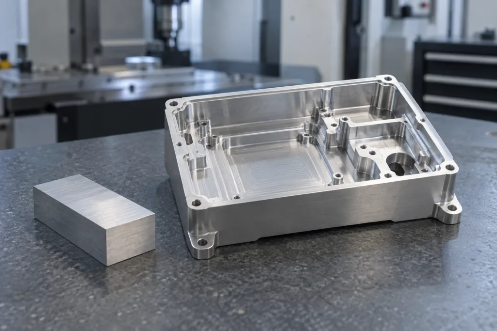
A versatile aluminum grade balancing machinability, strength and finishing options.
Explore details
A high-strength aluminum grade used where weight and mechanical performance are priorities.
Explore details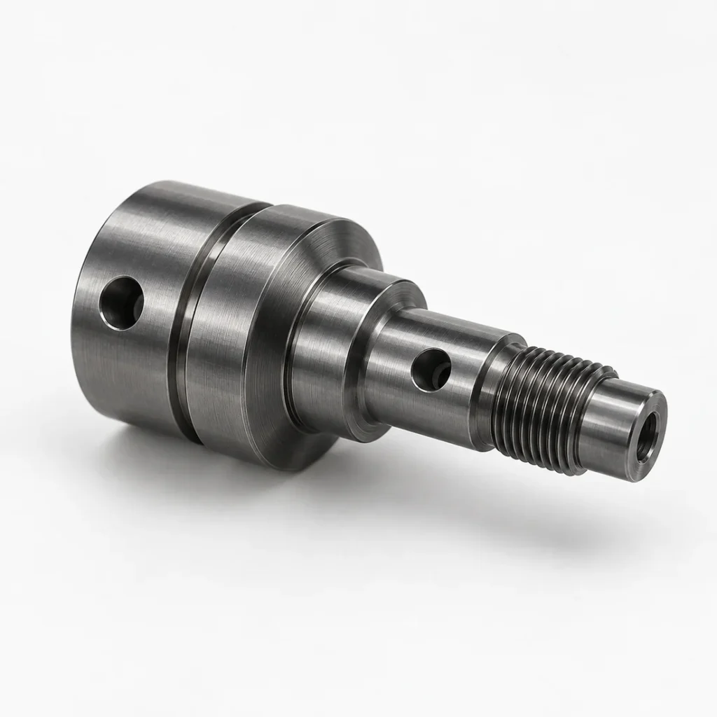
A broad family of strong, durable materials for shafts, tooling and industrial components.
Explore details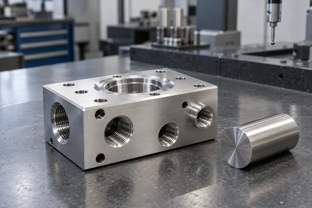
A widely used stainless grade offering corrosion resistance and practical fabrication characteristics.
Explore details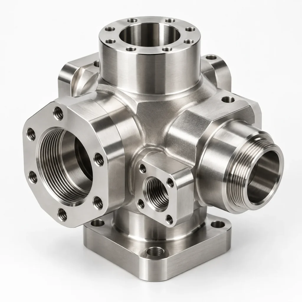
A corrosion-resistant stainless grade suited to demanding environments and fluid-handling components.
Explore details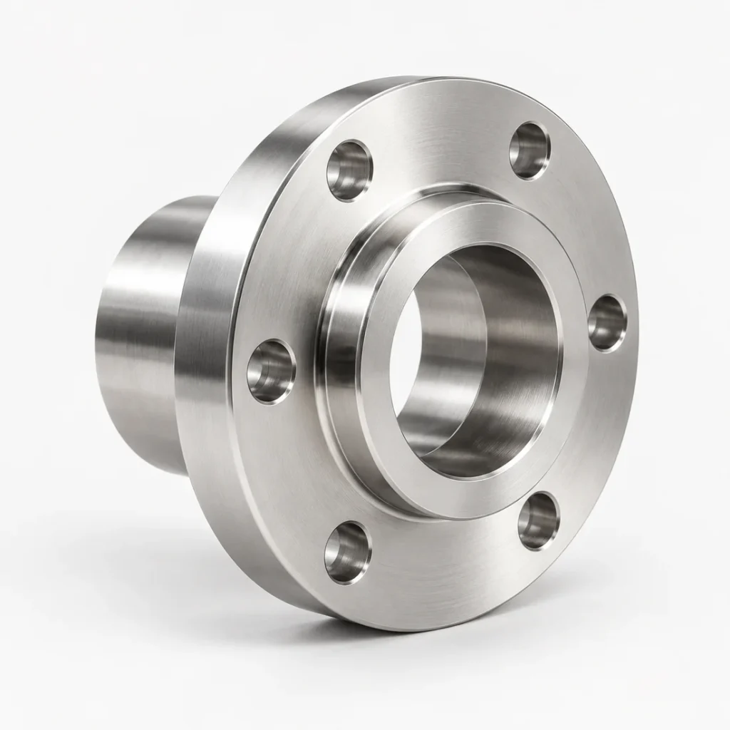
A precipitation-hardening stainless grade selected for strength and corrosion performance.
Explore details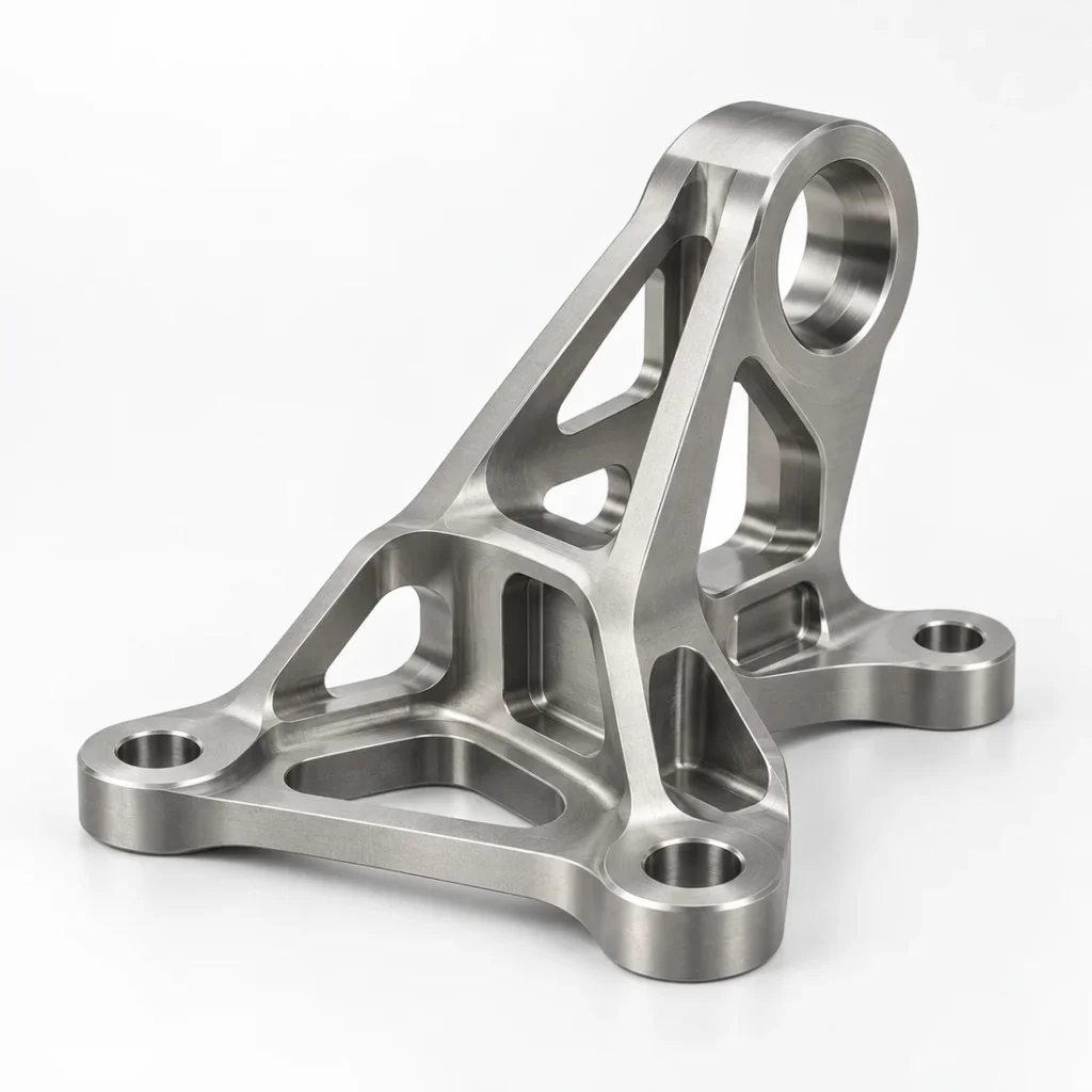
A titanium alloy used for lightweight, high-performance components in demanding applications.
Explore detailsApplications
Multi-face features and controlled datum relationships.
Confirmed metals and engineering plastics supported.
Fixture and inspection planning for repeat production.
Surface finishing
Preserves the cut surface and is often appropriate for functional interfaces after controlled deburring.
Requires grade, color, masking and thickness expectations to be agreed before machining allowances are set.
Compatibility depends on substrate and service environment; cosmetic acceptance should use an agreed visual standard.
Design guidance
Clearly mark datums, fit requirements and inspection priorities.
Expected quantities and repeat demand help guide process planning.
Finish selection can affect tolerances, masking and dimensional allowance.
Materials
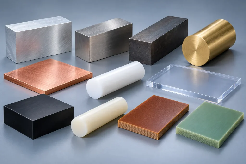
Aluminum generally permits productive material removal but still requires control of chip evacuation and thin-wall movement. Stainless and carbon steels place different demands on heat, cutter engagement and rigidity. Copper alloys vary widely, while engineering plastics need attention to heat, clamping pressure and moisture behavior.
The material article library provides general selection guidance. Actual grade availability and the production method are confirmed only after drawing review.
Verification
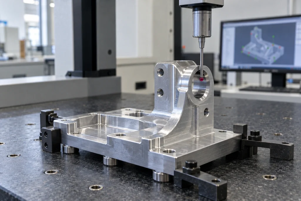
Milled parts often combine features produced from different orientations. Inspection planning therefore focuses on datum transfer, position, profile, flatness and bore relationships instead of checking isolated dimensions without functional context. Features that will be altered by finishing are identified so measurement occurs at the correct stage.
RFQ preparation
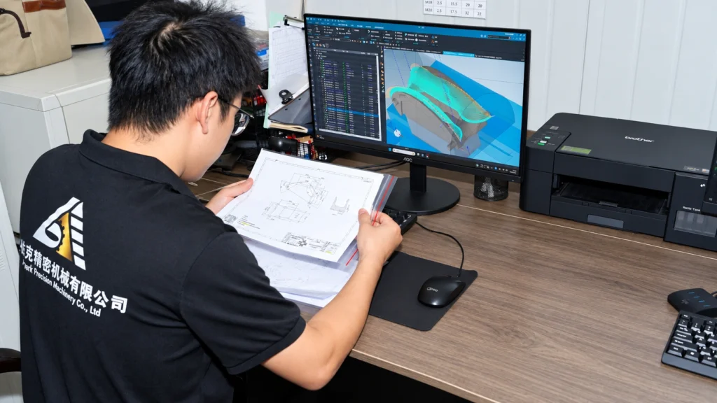
Provide the native 3D model together with a drawing that identifies datums, critical fits, threads, surface texture and geometric controls. Mark which pockets or channels are functional and which faces are cosmetic. Quantity affects fixture and toolpath decisions, so include prototype and anticipated repeat demand when known. If a finish follows machining, state coating type, color, masking and dimensions that apply after treatment. AYBERK uses this package to review setup count, cutter access, distortion risk and inspection before returning a manual quotation.
Production strategy
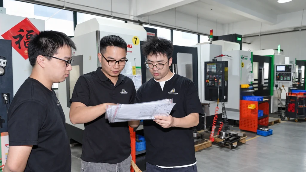
For a first article, the team may separate roughing, stabilization and finishing so movement can be observed before critical dimensions are completed. Once the route is proven, fixture references, tool data and inspection checkpoints support repeat production. A process change can still be necessary when quantity, stock form, drawing revision or finish changes. Repeatability therefore comes from controlled information and verified setup conditions, not from assuming that every future order is identical to the prototype.
Gallery
Frequently asked questions
Provide 3D CAD, a controlled 2D drawing, material grade and condition, quantity, finishing, inspection and documentation requirements. Mark critical features and the current revision. AYBERK reviews the package manually before issuing a quotation.
Yes. Tolerance capability is feature-, material-, geometry- and process-specific. The team reviews the actual drawing and identifies questions or manufacturing risks before confirming the quotation; a general website value is not used as automatic approval.
No. AYBERK does not display automatically calculated prices. Submit the project files through the RFQ page for an engineering review and formal quotation.
Related capability
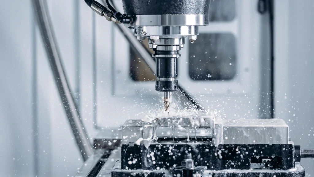
Custom CNC milling and turning for demanding metal and plastic components.
Explore details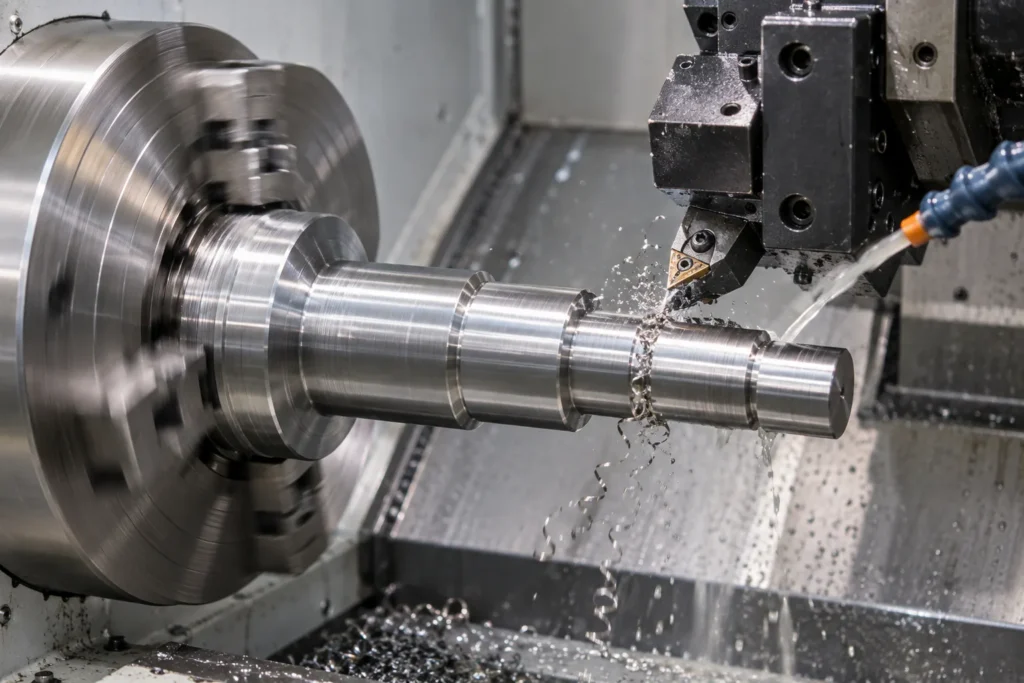
Precision turning for shafts, sleeves, bushings and rotational components.
Explore details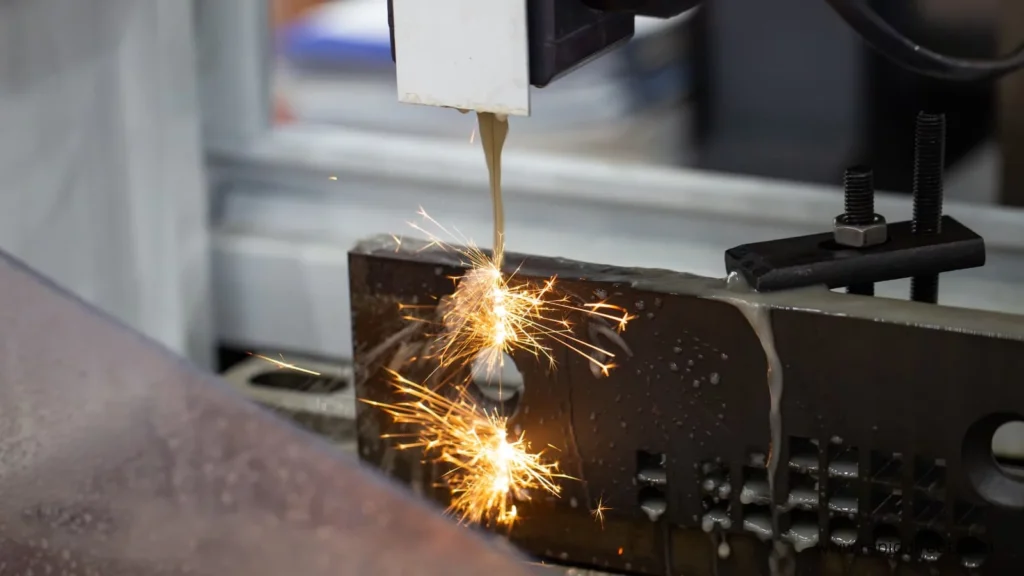
Controlled EDM processes for hardened materials, fine details and precision profiles.
Explore details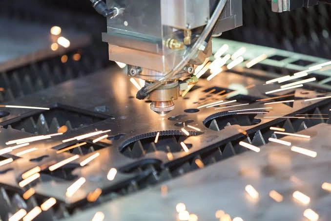
Prototype and production sheet metal parts with controlled forming and assembly.
Explore detailsEngineering review
Send the drawing, material requirement, quantity and inspection notes for a manual manufacturability and quotation review.