

Concentric feature control
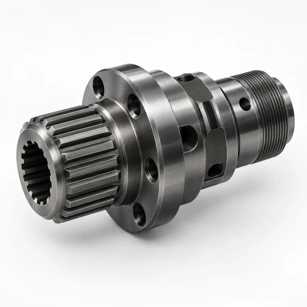
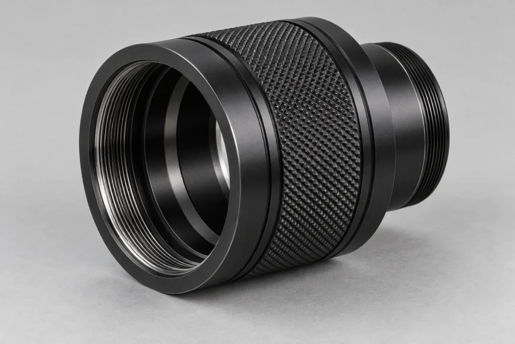
Turning is suited to shafts, sleeves, bores, threads and other rotational geometry.
Precision manufacturing capability
Precision turning for shafts, sleeves, bushings and rotational components.
Request a Quote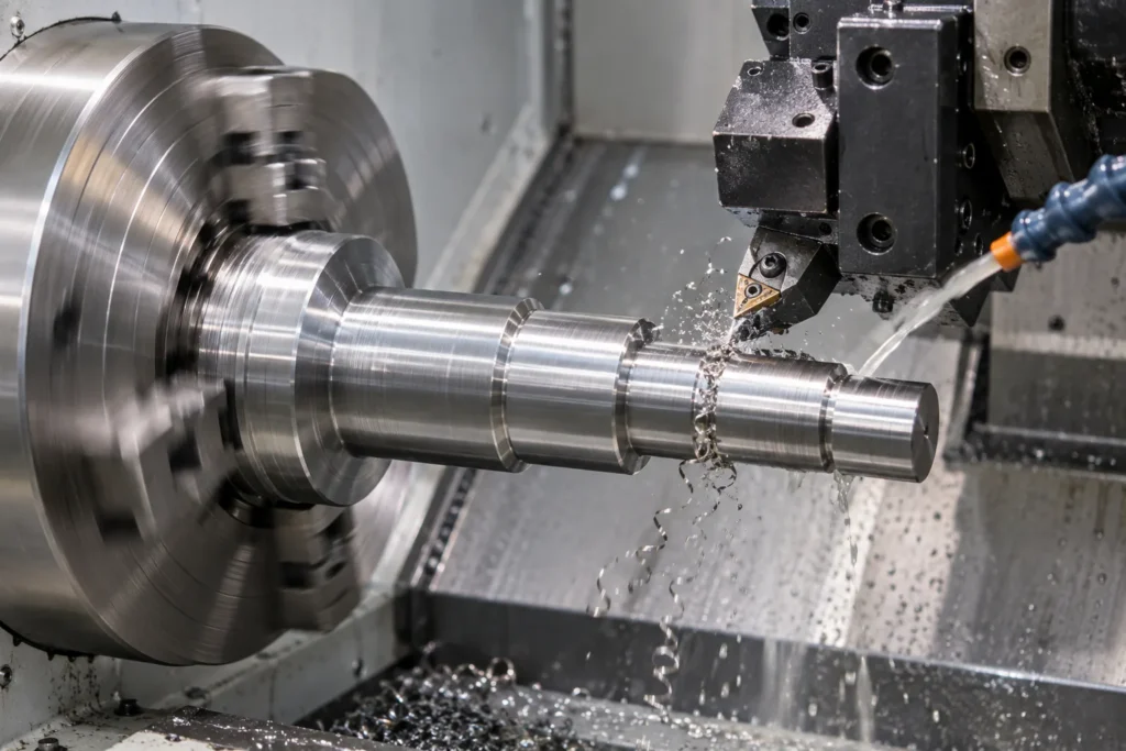
Process overview
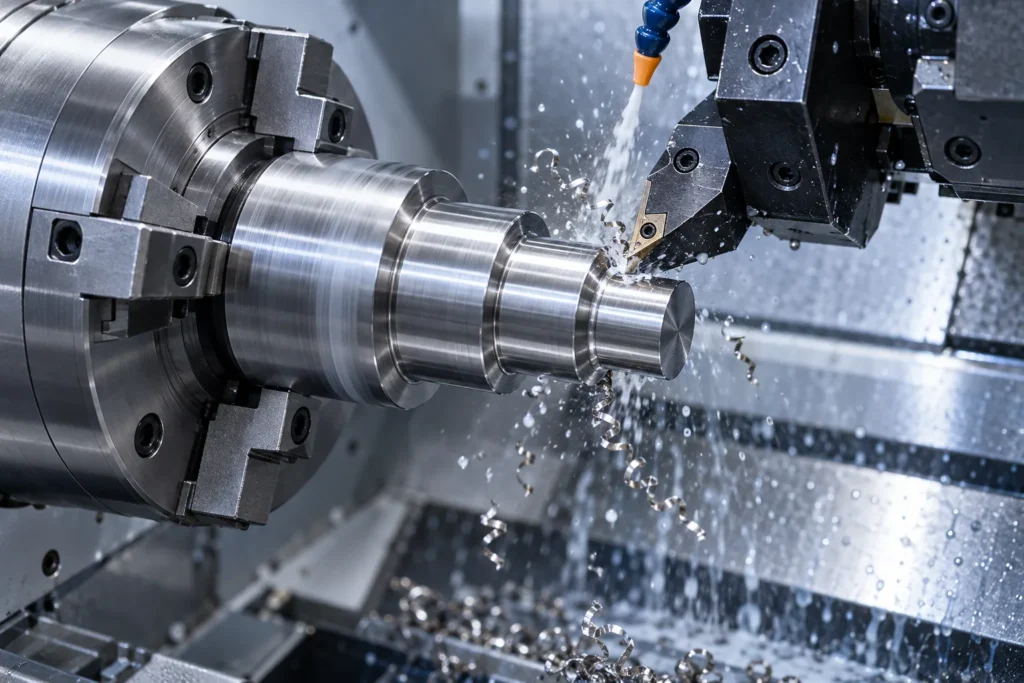
CNC turning rotates bar, tube or prepared stock while a controlled cutting tool creates diameters, shoulders, tapers, faces, grooves, bores and threads. Because the part rotates around the spindle axis, turning is especially effective when the functional geometry is predominantly cylindrical. Live tooling or coordinated milling may add flats, cross holes and key features, but the best route depends on how those secondary details relate to the turned datums.
Turning quality depends on more than nominal diameter. Stock straightness, chucking length, support, tool pressure, heat and the order of rough and finish cuts can affect cylindricity, runout and surface condition. Slender parts may need additional support or a changed sequence; thin rings can relax after material removal; deep bores require careful chip and tool management. AYBERK reviews these conditions against the actual drawing before agreeing the process and inspection plan.
Key advantages
Turning is suited to shafts, sleeves, bores, threads and other rotational geometry.
Tool paths are planned around stock condition, rigidity and surface requirements.
Cross holes, flats and milled details can be reviewed as part of the process route.
Production methods
Turning, facing, boring, threading and grooving operations are selected to match the drawing.
Combined operations can reduce handling where the component and available process route support it.
Technical capabilities
Values are published only after AYBERK confirms the applicable process scope. Send your drawing for project-specific review.
Manufacturing workflow
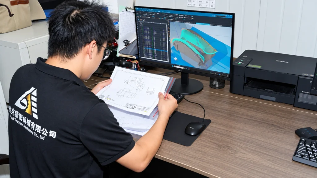
Drawing requirements, critical features and production intent are reviewed before setup.

Machining, in-process checks and documentation follow the agreed project requirements.
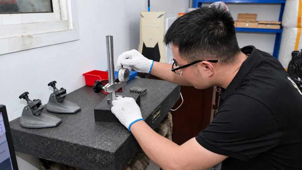
Finished parts are checked against the drawing before release and export packing.
Related capability
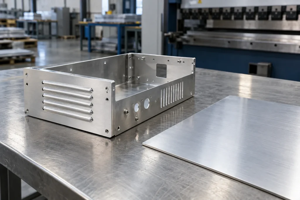
A corrosion-resistant aluminum grade frequently selected for formed and machined components.
Explore details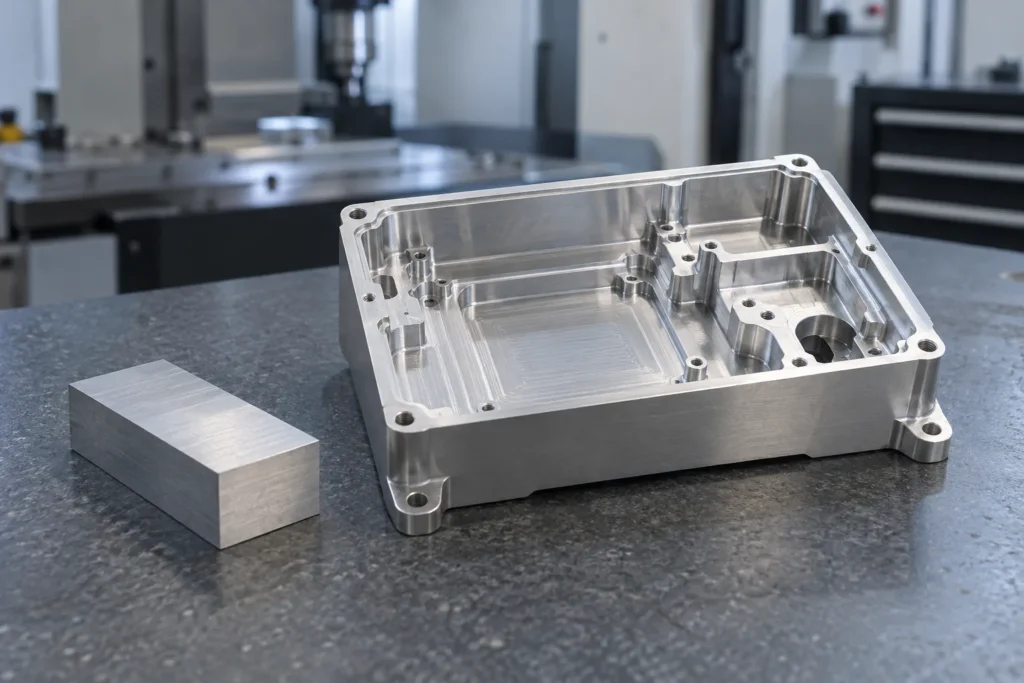
A versatile aluminum grade balancing machinability, strength and finishing options.
Explore details
A high-strength aluminum grade used where weight and mechanical performance are priorities.
Explore details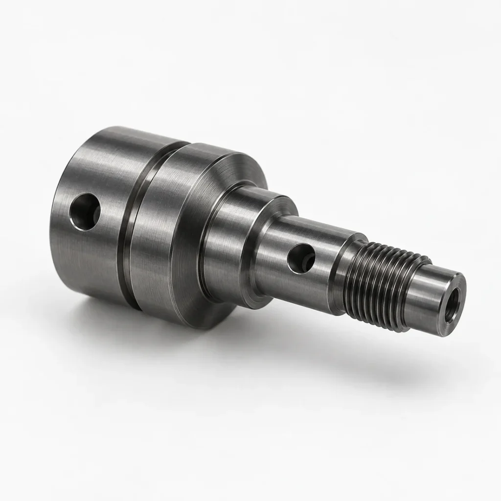
A broad family of strong, durable materials for shafts, tooling and industrial components.
Explore details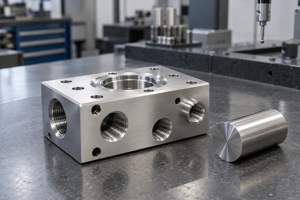
A widely used stainless grade offering corrosion resistance and practical fabrication characteristics.
Explore details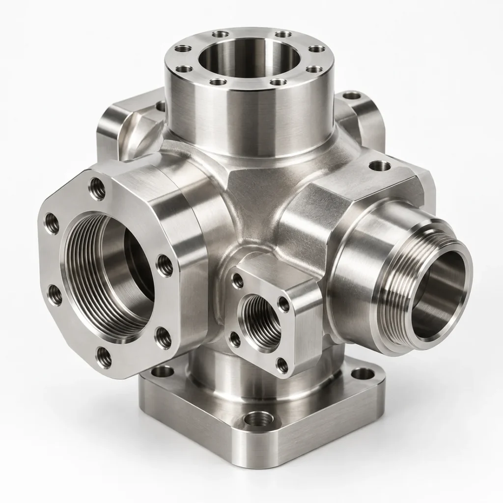
A corrosion-resistant stainless grade suited to demanding environments and fluid-handling components.
Explore details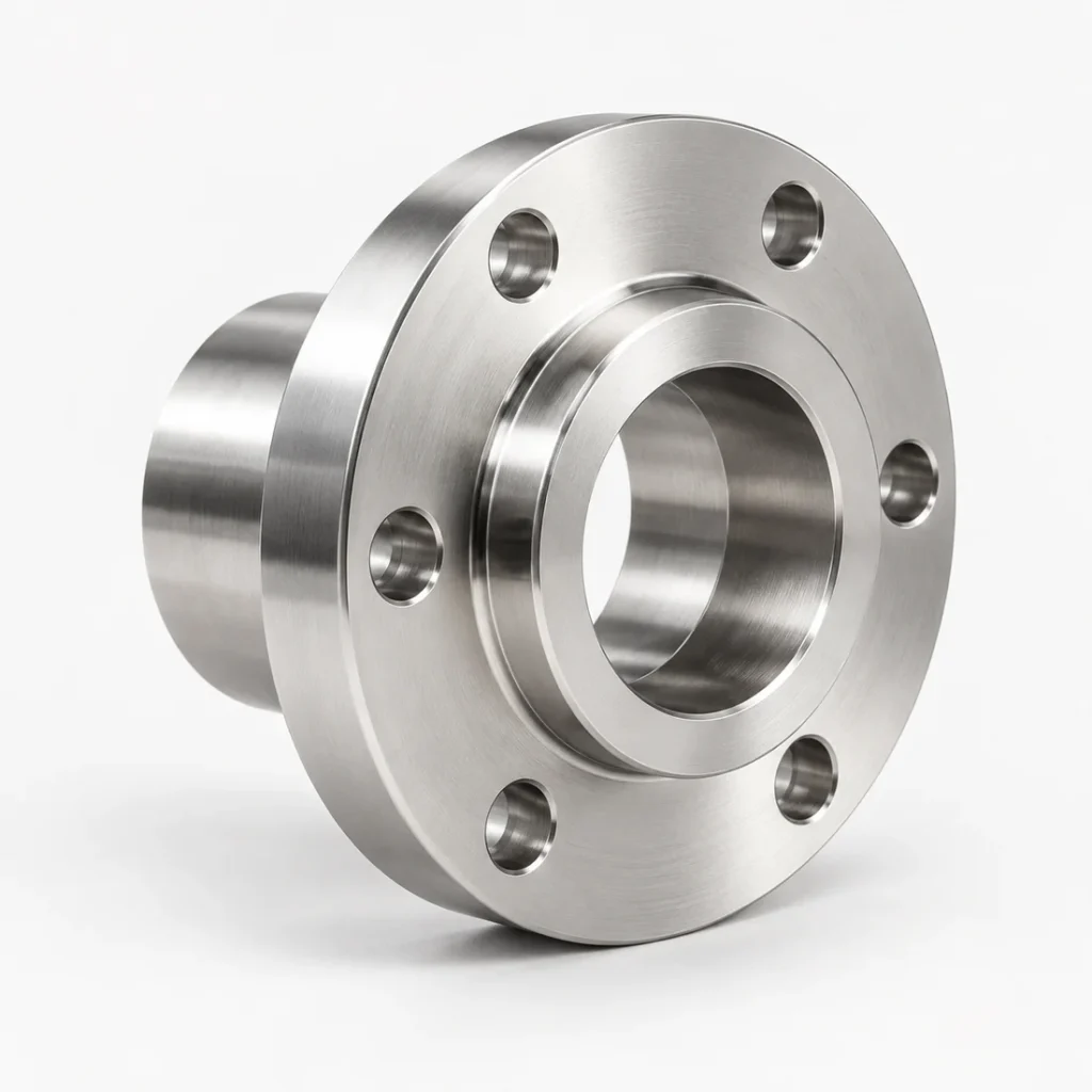
A precipitation-hardening stainless grade selected for strength and corrosion performance.
Explore details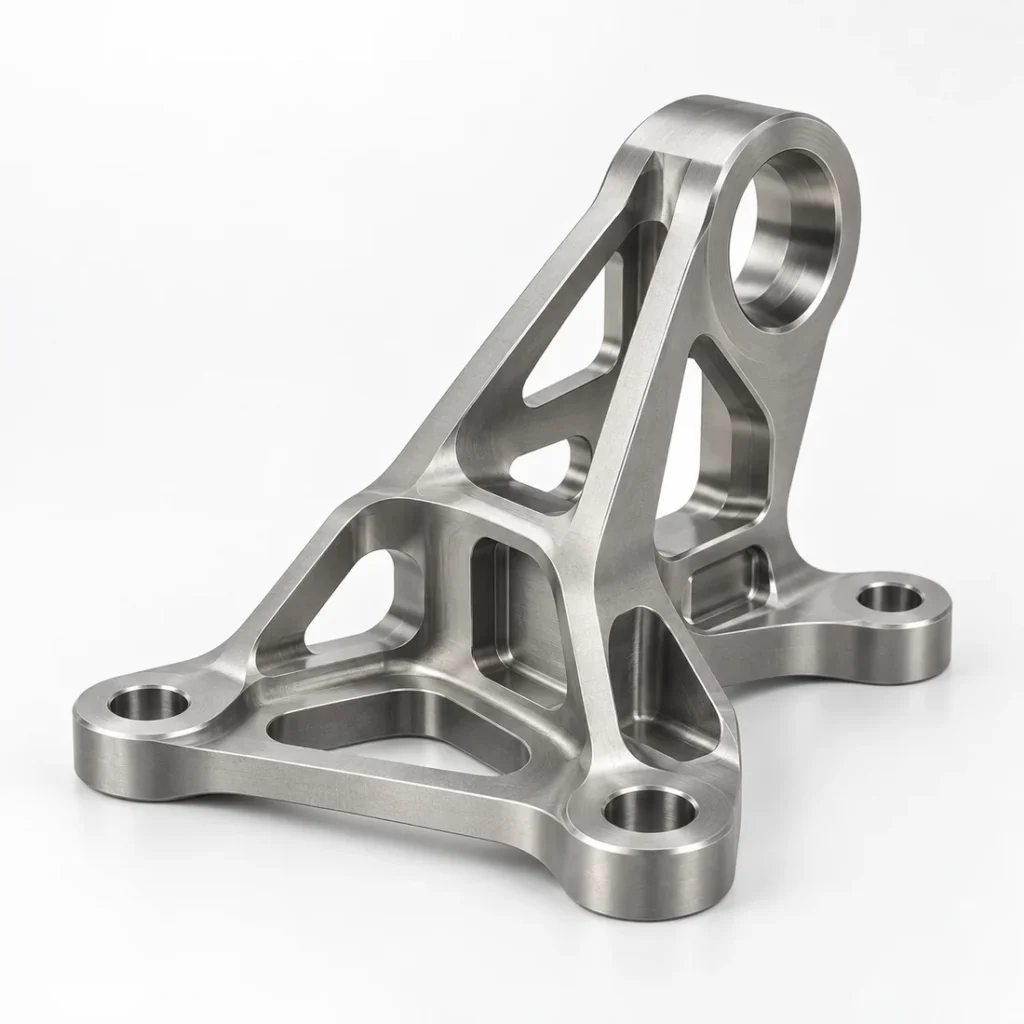
A titanium alloy used for lightweight, high-performance components in demanding applications.
Explore detailsApplications
Profiles, bores, threads and concentric features.
Cross holes and milled details can be coordinated where required.
Critical diameters and runout requirements are reviewed from the drawing.
Surface finishing
Toolpath, insert and feed are selected around the drawing surface requirement and subsequent assembly function.
Where specified, stock allowance and datum protection must be agreed before machining. These are not assumed operations.
Material compatibility, thread masking and dimensional build are reviewed before the final route is confirmed.
Design guidance
Clearly mark datums, fit requirements and inspection priorities.
Expected quantities and repeat demand help guide process planning.
Finish selection can affect tolerances, masking and dimensional allowance.
Materials
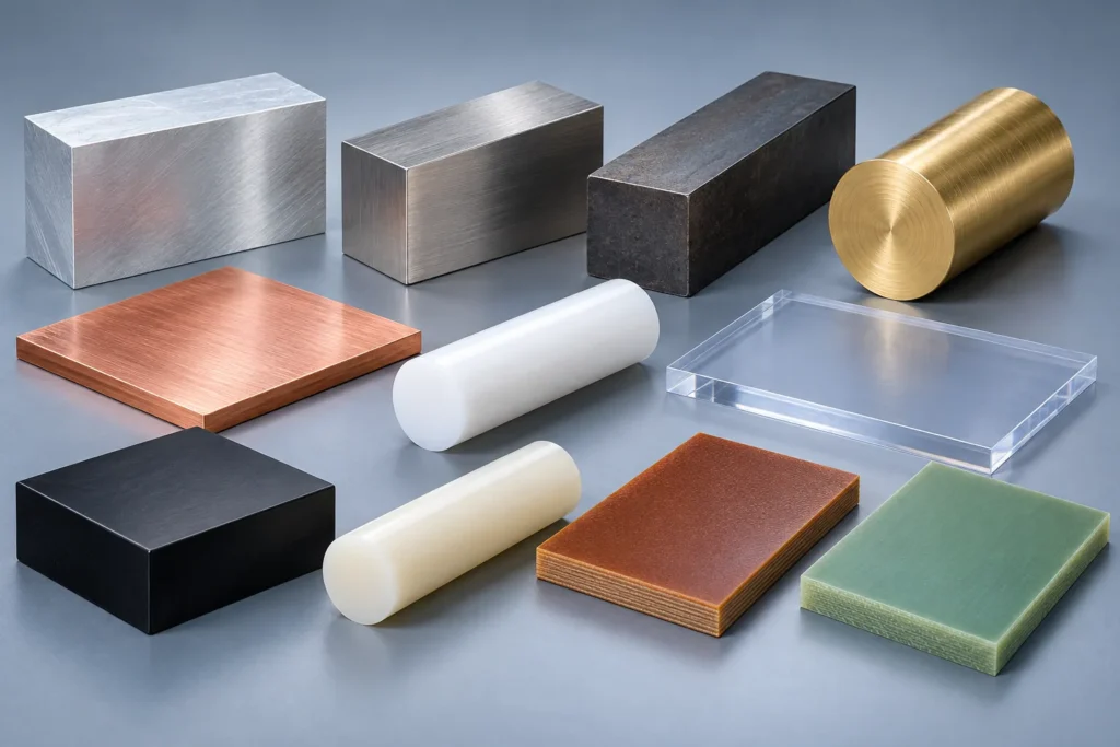
Free-machining alloys and stable bar stock behave differently from gummy copper, work-hardening stainless or moisture-sensitive plastic. The selected insert, support and cutting conditions must match the actual grade and stock condition. Heat treatment after roughing can also change the sequence and finish allowance.
Material alternatives are discussed only as engineering options. AYBERK confirms availability and the final production route during RFQ review.
Quality
Turning inspection commonly links diameters, faces, bores and threads back to a primary axis or seating surface. The measurement setup must therefore reproduce the intended datum condition. For thin or flexible parts, measuring force and support can be as important as instrument resolution.

RFQ preparation
The RFQ should state material condition, starting stock preference if controlled, quantity, heat treatment, finish and required certificates. Identify the primary datum axis, functional fits, thread standard and gauge requirement, and any cross holes or flats that must relate to the turned features. For long parts, provide straightness, runout and support constraints rather than relying on a model alone. These details allow AYBERK to compare bar-fed, chuck-based and secondary-machining routes without making unsupported assumptions. State whether mating parts or gauges are available for a functional review.
Production strategy
A rotational part can change when heavy stock is removed, when it is released from the chuck or when heat treatment occurs between operations. The route may therefore leave finish allowance, reverse the part onto a protected datum or use a separate operation for a critical bore or seating face. Threads and grooves are scheduled so they remain accessible and can be gauged. For repeat work, jaw condition, support method and measurement setup are controlled alongside the program.
Gallery
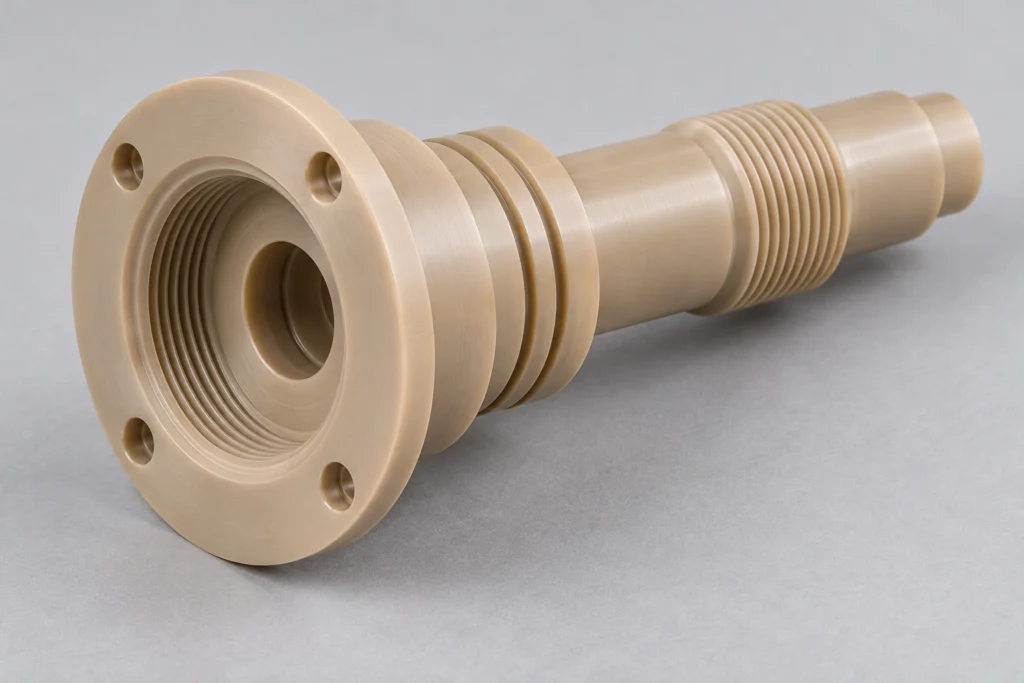
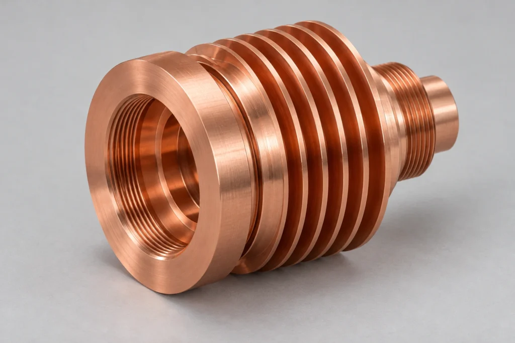
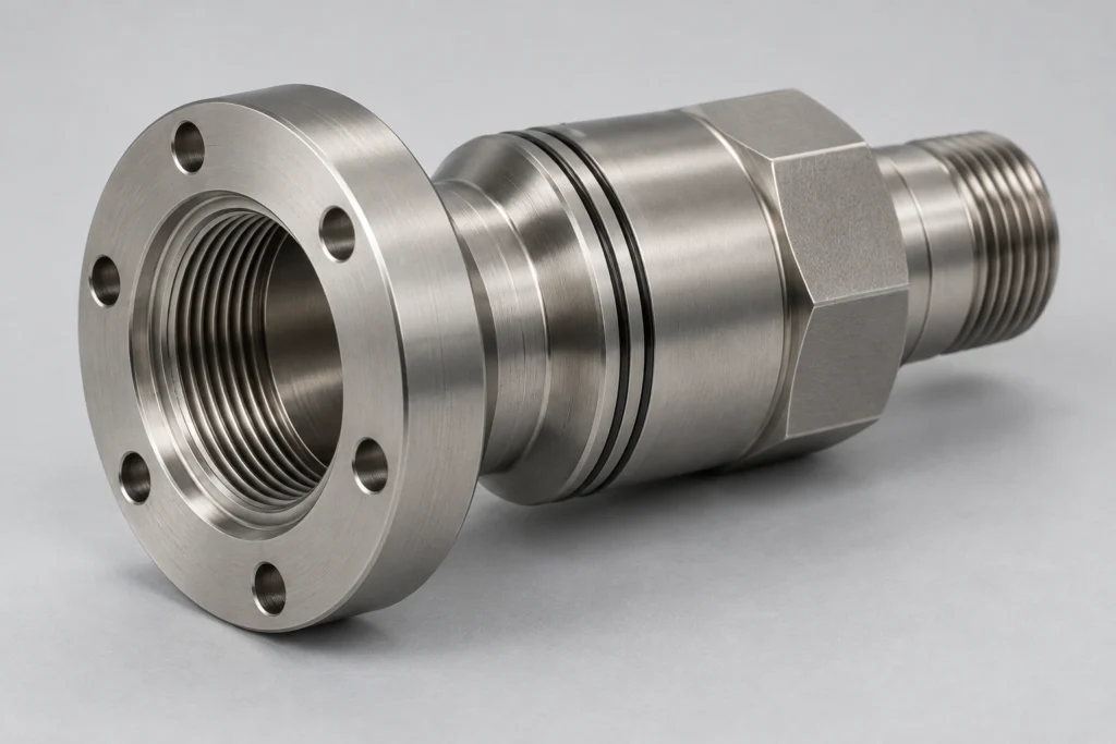
Frequently asked questions
Provide 3D CAD, a controlled 2D drawing, material grade and condition, quantity, finishing, inspection and documentation requirements. Mark critical features and the current revision. AYBERK reviews the package manually before issuing a quotation.
Yes. Tolerance capability is feature-, material-, geometry- and process-specific. The team reviews the actual drawing and identifies questions or manufacturing risks before confirming the quotation; a general website value is not used as automatic approval.
No. AYBERK does not display automatically calculated prices. Submit the project files through the RFQ page for an engineering review and formal quotation.
Related capability
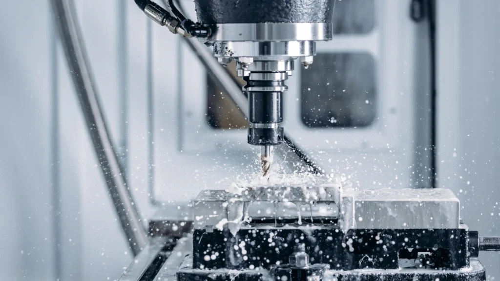
Custom CNC milling and turning for demanding metal and plastic components.
Explore details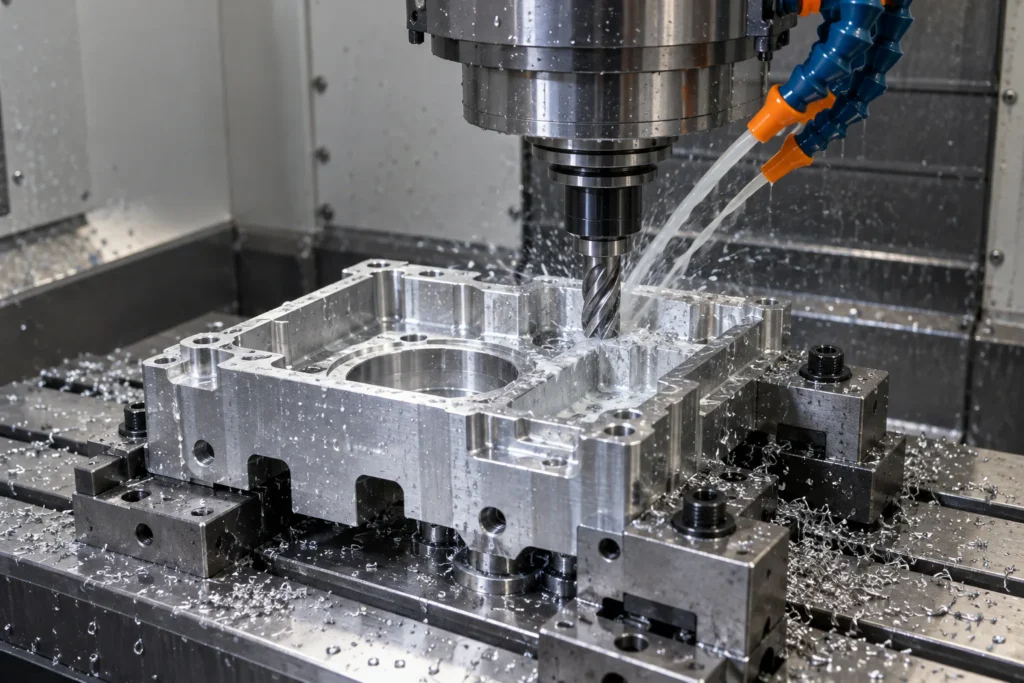
Precision milling for housings, brackets, plates and complex prismatic components.
Explore details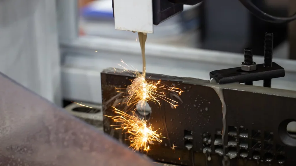
Controlled EDM processes for hardened materials, fine details and precision profiles.
Explore details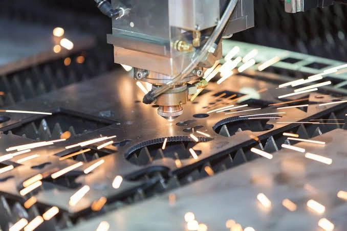
Prototype and production sheet metal parts with controlled forming and assembly.
Explore detailsEngineering review
Send the drawing, material requirement, quantity and inspection notes for a manual manufacturability and quotation review.